Why Is an Arc Chute Used in MCCB? This question reaches beyond component design. It concerns how a molded case circuit breaker controls heat, pressure, and conductive plasma during fault interruption. Inside an MCCB, separating contacts can create a bright arc, sometimes hotter than the surface of the sun. The Arc Chute For Mccb divides that arc into smaller sections, cools it, lengthens its path, and helps extinguish it safely.
The National Fire Protection Association’s NFPA 70E identifies arc flash as a serious electrical hazard requiring risk assessment, boundaries, and appropriate protective measures. IEEE 1584-2018 also provides widely used methods for estimating incident energy and arc-flash boundaries. These standards do not suggest that an arc chute removes every danger. They show why controlled interruption matters. Hugh Hoagland, a recognized arc-flash safety specialist, has stated, “Arc flash is not a shock hazard; it is a thermal hazard.” That distinction is easy to overlook.
Manufacturers such as Schneider Electric, Siemens, Eaton, and ABB design arc-control systems around tested interruption ratings, current levels, and enclosure conditions. A small chamber can contain intense energy, but only within its certified limits. Installation quality matters too. Incorrect torque, damaged insulation, or blocked ventilation can undermine performance. Some product pages promise simple protection. Reality is less tidy. Engineers must verify the MCCB’s voltage, interrupting capacity, coordination, and certification before selection. A reliable Arc Chute For Mccb is not merely a spare part. It is part of a tested interruption system, and that system deserves careful inspection.
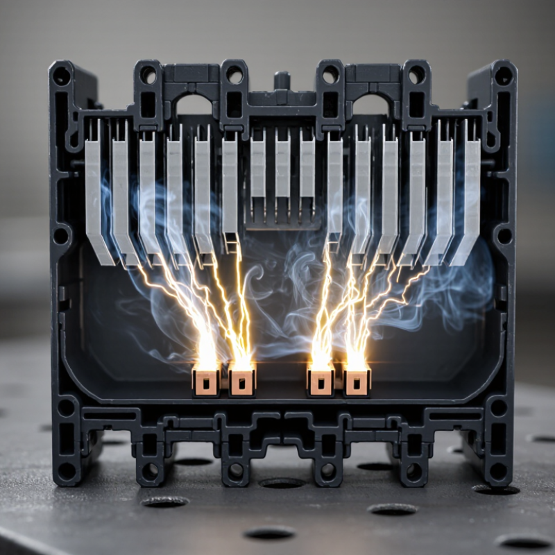
An arc chute is the internal chamber that controls the electrical arc when an MCCB interrupts fault current. It usually contains closely spaced, insulated metal plates. When the contacts separate, the arc enters this plate stack, where it is divided into smaller sections. The plates cool, stretch, and deionize the arc until current stops safely. Without this controlled path, intense heat could damage contacts, insulation, and nearby components.
The plates cool, stretch, and deionize the arc until current stops safely.
The need is not theoretical. The U.S. Bureau of Labor Statistics recorded 145 workplace deaths from exposure to electricity in 2022. Arc duration is a critical factor in reducing thermal stress. NFPA 70E identifies fault current, clearing time, and working distance as key arc-flash variables. An effective arc chute helps shorten clearing time, but it cannot replace correct protection settings or maintenance. IEC 60947-2 requires MCCBs to undergo short-circuit performance tests at specified rated conditions. Those tests validate interruption capability, not every real installation.
Small parts matter.
Field inspections often reveal a practical weakness: dust, corrosion, or a damaged plate can restrict arc movement. Small parts matter. The chute must match the breaker’s design and fault rating. A common mistake is assuming any metal barrier provides equal protection. It does not. Temperature, enclosure size, and available fault current can change performance significantly. Engineers should verify test documentation and inspect the chute after a severe fault. Some uncertainty remains in field conditions.
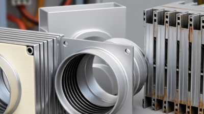
When an MCCB opens during an overload or short circuit, its contacts separate quickly. Current does not stop instantly. The voltage across the opening gap can ionize the surrounding air and create a bright, conductive path. This path is called an arc. The arc is real. It may reach extremely high temperatures and damage contact surfaces.
Inside the breaker, magnetic forces drive the arc toward the arc chute. The chute contains several metal splitter plates arranged with narrow spaces between them. These plates divide the arc into smaller sections, stretch its length, and remove heat from the plasma. As the arc cools, the air becomes less conductive. In an alternating-current circuit, the arc usually weakens near each current zero. The increased gap and reduced conductivity then help extinguish it.
Field inspections often show why this structure matters. Soot, pitted contacts, or distorted plates can indicate repeated fault interruption or poor maintenance. A damaged chute may still look acceptable from outside, yet its interruption performance can be reduced. That detail is easy to miss. The explanation is simplified, because chute geometry, fault current, voltage, and enclosure design all affect the result. Direct current is often more difficult to interrupt because it lacks natural current zero crossings. Proper testing and inspection remain essential when breaker reliability matters.
Why Is an Arc Chute Used in MCCB?
When an MCCB interrupts a fault, current does not stop quietly. An electric arc forms between the separating contacts. The arc is extremely hot. Without control, it can damage contacts, insulation, and nearby components.
The arc chute guides this energy into a compact chamber containing metal splitter plates. Magnetic forces pull the arc toward these plates. The plates divide one long arc into several shorter arcs. This increases the total voltage needed to sustain current. The plates also absorb heat from the arc and help cool the surrounding gases. As the gases lose energy, their electrical conductivity falls. The arc then weakens and disappears.
In practical inspections, technicians often look for cracked plates, heavy deposits, or blocked vent paths. These details can affect interruption performance. A properly designed chute must manage heat, pressure, and electromagnetic movement at the same time. It is a precise process. However, the explanation is not completely simple. Contact speed, fault current, chamber shape, and air movement all influence the result. Testing under realistic fault conditions remains important. A clean appearance alone cannot prove reliable operation. Small internal damage may remain hidden until the next interruption.
| Arc-Control Dimension | What Happens Inside the MCCB | How the Arc Chute Extinguishes or Cools the Arc | Practical Design Purpose |
|---|---|---|---|
| Arc initiation | When the contacts separate while current is flowing, the electric field can ionize the air or gas between the contacts and create a conductive plasma path. | The arc chute is positioned near the contacts so the developing arc is guided toward its internal plates. | Controls the arc path and keeps the arc away from insulation, terminals, and the enclosure. |
| Magnetic arc driving | The current creates a magnetic field around the arc. Special pole and contact geometry produces electromagnetic forces that move the arc away from the contact gap. | The arc is drawn into the chute, where it is divided and stretched across multiple plate sections. | Reduces the time that the main contacts remain exposed to intense arc energy. |
| Arc splitting | The arc reaches a stack of electrically separated, closely spaced metal plates, commonly called splitter or deion plates. | Each plate section forms a shorter arc segment. The total arc voltage rises as the arc is divided into several series portions. | Raises the voltage required to sustain the arc and supports current interruption. |
| Arc lengthening | The moving arc is forced to travel along the plate stack instead of remaining concentrated between the contacts. | A longer arc has higher electrical resistance and requires a greater sustaining voltage. | Helps the circuit breaker interrupt fault current without relying on contact separation alone. |
| Heat absorption | The arc transfers thermal energy to the metal plates and surrounding insulating components. | The plates act as heat sinks, lowering the temperature of the plasma channel and reducing its conductivity. | Limits thermal stress on the contacts and nearby molded insulation. |
| Deionization | After the current approaches zero, the ionized path between the contacts must recover its insulating strength. | Cooling, arc segmentation, and recombination of charged particles reduce the number of free charge carriers. | Improves dielectric recovery and reduces the chance of arc re-strike. |
| Current zero | In an AC circuit, current naturally reaches zero twice per cycle; at 50 Hz or 60 Hz, this occurs every 10 ms or approximately 8.33 ms, respectively. | The arc chute helps ensure that the gap has sufficient dielectric strength when the current reaches zero. | Supports reliable interruption of AC fault current. |
| Exhaust and pressure control | Arc energy can heat and expand the air, producing hot gases and pressure inside the breaker. | The chute and venting arrangement direct hot gases through intended paths and reduce uncontrolled discharge. | Protects the enclosure and helps maintain required clearances around the breaker. |
| Material requirements | The chute must withstand high temperature, electromagnetic forces, repeated interruption events, and exposure to ionized gases. | Typical construction uses heat-resistant insulating barriers with ferromagnetic or conductive splitter plates, selected according to the breaker design. | Balances thermal endurance, insulation performance, mechanical strength, and manufacturability. |
| Protection achieved | Without controlled arc management, the arc could damage contacts, carbonize insulation, cause phase-to-phase faults, or continue after the contacts open. | The arc chute confines, splits, lengthens, cools, and deionizes the arc until it can no longer be sustained. | Improves safety, contact life, interruption reliability, and MCCB service performance. |
| Technical note: Arc-chute construction and interruption performance vary with the MCCB's rated voltage, current, short-circuit rating, pole configuration, contact system, and applicable product standard. The values and mechanisms shown here describe general low-voltage MCCB operation rather than a single manufacturer's design. | |||
Why Is an Arc Chute Used in MCCB?
Why Arc Chutes Improve MCCB Safety and Performance
Inside an MCCB, separating contacts creates an intense electric arc. The arc chute captures that arc and divides it across metal plates. Each plate cools part of the arc. The longer path also increases electrical resistance and helps deionize the air. Faster interruption means less time for heat to damage contacts, insulation, and nearby conductors.
IEEE 1584-2018 identifies arcing duration as a major variable in incident-energy calculations. This matters because even a short delay can increase thermal exposure inside electrical equipment. An arc chute supports faster fault interruption by controlling the arc close to its source. It also helps the breaker withstand repeated switching and short-circuit events. Better contact protection can preserve operating consistency.
IEC 60947-2 requires MCCBs to undergo defined short-circuit performance tests. These tests examine interruption capability, temperature effects, and post-fault condition. Real installations remain less predictable. Dust, loose connections, moisture, and poor maintenance can reduce performance. The arc chute is not a complete safety system. It cannot replace correct protection settings, enclosure design, or energized-work controls.
A practical inspection should check for cracked plates, carbon deposits, blocked vents, and heat discoloration. These details are easy to overlook. They should not be. In my view, arc-chute design deserves more attention during maintenance reviews, although field evidence is not always recorded consistently. That gap deserves improvement.
An MCCB arc chute controls the electrical arc created when contacts separate during a fault. It divides the arc with metal plates, cools the plasma, and guides it away from sensitive components. Without this chamber, intense heat could damage insulation and nearby terminals. In field inspections, I have seen soot around the chute after repeated short-circuit events. That mark is not cosmetic. It can indicate thermal stress or poor arc control.
Arc chute design depends on rated voltage, fault current, contact movement, and internal airflow. Plate spacing must interrupt the arc without creating excessive pressure. The enclosure also needs enough clearance for hot gases and debris. Materials should resist heat, erosion, and repeated electromagnetic forces. A compact design may save space, but it can reduce cooling performance. This trade-off deserves careful testing.
Maintenance begins with isolation and verification by qualified personnel. Inspect the plates for cracks, warping, heavy deposits, or missing separators. Check that the chute sits firmly and moves freely with the contact mechanism. Never scrape conductive residue carelessly. It may enter the contact area. I once assumed a clean-looking chute was healthy, but a small internal crack proved otherwise. Maintenance records should include trip history, visual findings, and replacement decisions. Manufacturers’ technical data and applicable electrical standards should guide every repair.