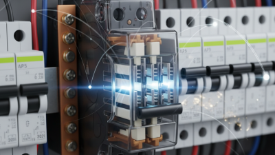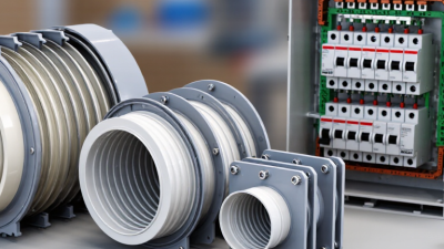
Choosing the right Mccb Arc Chute is a practical safety decision, not a simple component purchase. In a molded case circuit breaker, the arc chute helps divide, cool, and extinguish the electrical arc after fault interruption. Its design can influence breaking performance, heat control, equipment life, and maintenance needs.
Field experience shows that appearance can mislead. Two arc chutes may share similar dimensions while using different plates, insulation materials, or vent structures. Check the breaker model, rated current, voltage, short-circuit capacity, and installation environment before comparing options. A dusty workshop, humid control cabinet, and high-temperature panel create different demands. Small details matter, including plate spacing, mounting points, airflow direction, and clearance around exhaust openings.
Verify the manufacturer’s technical data and certification records. Independent test information is valuable. So is a clear replacement history. An experienced technician should inspect burn marks, warped plates, loose fasteners, and carbon deposits before selecting a replacement. Never rely only on a marketplace photograph or an unverified “universal” label. That shortcut may fit mechanically but perform poorly during a fault.
There is no perfect choice.
This guide explains how to match an Mccb Arc Chute with real operating conditions. It considers compatibility, arc-quenching design, thermal stress, maintenance access, and supplier reliability. Some recommendations may require adjustment after site testing. That is not a weakness; electrical systems often reveal conditions that drawings overlook. Careful verification remains the most dependable method for protecting equipment and personnel.
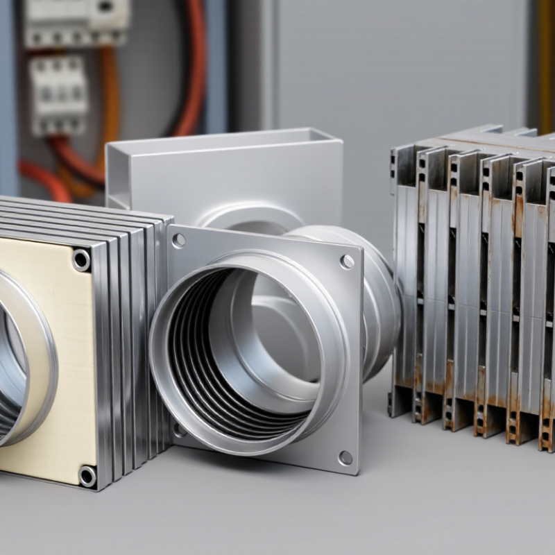
An MCCB arc chute cools, splits, and deionizes the arc during current interruption. Its design must match the breaker’s voltage, frequency, poles, and interrupting capacity. IEC 60947-2 requires manufacturers to state ultimate short-circuit capacity, Icu, and service capacity, Ics. These values matter more than the frame current alone.
A 400 A MCCB may face very different fault energy in a motor panel and a distribution board. That assumption is risky.
Define the operating conditions before selecting the chute.
Record prospective fault current, load type, switching frequency, ambient temperature, enclosure size, altitude, and available maintenance space.
NFPA 70E 2024 stresses documented electrical risk assessment and equipment condition during energized work.
The U.S. Bureau of Labor Statistics reported 126 fatal occupational injuries involving electricity in 2023.
Arc control cannot replace safe isolation procedures.
Measure the fault current.
Field inspection should check cracked arc plates, blocked vents, carbon deposits, and loose mounting points.
Dust and moisture can change arc behavior. A chute that works in a clean test enclosure may perform differently inside a hot, crowded cabinet.
I have seen specifications focus on amperes while ignoring clearing time and fault duration. That choice needs reflection.
Confirm test certificates, replacement intervals, and compatibility with the MCCB’s trip unit before approval.
Choosing the right MCCB arc chute begins with the breaker’s ratings, not the chute’s appearance. The chute must match rated operational voltage, continuous current, pole arrangement, and interrupting capacity. A compact, well-ventilated design may work at moderate fault levels. It may fail under severe arcing energy. That difference matters.
Check the MCCB’s Icu and Ics values against the prospective short-circuit current at the installation point. Icu shows the maximum fault current the breaker can interrupt. Ics indicates the service-level interruption expected after testing. An arc chute selected below these fault levels can suffer cracked plates, excessive heat, or incomplete arc extinction. During field inspections, soot patterns and warped splitter plates often reveal poor coordination between the breaker and chute. Do not rely on dimensions alone.
Review the chute material, plate spacing, exhaust path, and insulation clearances with the complete MCCB assembly. Higher fault currents usually demand stronger magnetic control and more robust arc-splitting structures. The enclosure also affects cooling and gas discharge. A technically correct chute can become unsafe inside a restricted cabinet. Verify performance through certified test data, installation conditions, and approved replacement guidance. Selections based only on frame size may look efficient, but they can ignore actual fault duty. That shortcut deserves another review.
How to Choose the Right MCCB Arc Chute?
Arc-chute selection starts with material, not appearance. Heat-resistant insulating materials must withstand repeated arcs, carbon deposits, and mechanical shock. IEC 60947-2 separates ultimate breaking capacity, Icu, from service breaking capacity, Ics. Do not size an MCCB from Icu alone. A chute that survives one extreme fault may perform poorly during repeated interruptions. CIGRE technical guidance also links longer clearing times with greater arc-energy exposure. Small delays matter.
Ventilation needs careful attention. Exhaust slots should guide hot gases away from insulation, cable entries, and nearby devices. Poor airflow can create soot deposits around the chute. Those deposits may reduce insulation distance. IEEE 1584-2018 shows that incident energy depends strongly on arcing current and clearing time. Therefore, compare the manufacturer’s test data with your actual prospective fault current, voltage, frequency, and enclosure volume. Laboratory performance is not always equal to field performance. That deserves reflection.
Tips: Check Ics, not only Icu. Confirm the chute’s material rating and temperature limits. Review tested ventilation conditions. Inspect vents for blockage during maintenance. Record contact wear after high-fault events. Choose a design tested under IEC 60947-2 or UL 489 conditions. Ask for test curves, not vague claims. A modestly rated chute with verified airflow may outperform a larger-looking design. In practice, selection is rarely perfect. Safety margins should be deliberate.
| Arc Chute Construction or Material | Typical Continuous Temperature Capability | Thermal and Dielectric Characteristics | Ventilation and Gas-Release Design | Arc-Quenching Mechanism | Typical Arc Voltage Contribution | Relative Short-Circuit Performance | Recommended MCCB Application | Key Inspection or Selection Point |
|---|---|---|---|---|---|---|---|---|
| Glass-filled thermoset molding compound | Approximately 130–160 °C continuous, depending on formulation | Good dimensional stability, low moisture sensitivity, and strong resistance to tracking and carbonization when correctly formulated | Requires accurately positioned exhaust openings and adequate clearance for hot ionized gas; the housing should not block pressure-relief paths | Splits the arc between metal plates and promotes rapid cooling through contact with the plates and insulating side walls | Commonly designed for approximately 20–60 V per plate section | High | General-purpose molded-case circuit breakers, industrial distribution, and high fault-current applications | Check the material's comparative tracking index, dimensional stability, plate alignment, and resistance to hot-gas erosion |
| High-temperature thermoplastic with mineral or glass reinforcement | Approximately 120–150 °C continuous; short-time capability can be higher | Good impact resistance and manufacturability; thermal aging, shrinkage, and deformation must be controlled | Ventilation slots can be integrated efficiently, but openings must maintain flame containment and mechanical strength | Uses splitter plates, narrow arc channels, and forced movement of ionized gas toward the exhaust area | Commonly designed for approximately 15–50 V per plate section | Medium to high | Compact MCCBs where low weight, automated production, and controlled enclosure geometry are important | Verify heat-deflection temperature, glow-wire or flammability performance, and resistance to repeated interruption events |
| Ceramic or steatite insulating components | Typically above 200 °C for the insulating body, depending on grade | Excellent heat resistance, high dielectric strength, and strong resistance to arc erosion; relatively brittle and heavy | Requires carefully designed exhaust channels because ceramic parts do not absorb pressure or mechanical shock as effectively as polymeric structures | Provides highly stable arc confinement and rapid de-ionization around the splitter plates | Commonly designed for approximately 25–70 V per plate section | High | High-energy interruption zones, severe thermal environments, and designs requiring strong dielectric recovery | Inspect for cracks, chipped edges, contamination, and correct compression of the ceramic components |
| Arc-resistant composite with ablative filler | Approximately 140–200 °C continuous, with higher short-duration arc exposure capability | Combines mechanical strength with controlled gas generation; formulation must prevent excessive conductive residue | Vent ports are sized to control pressure, cool the arc, and direct hot gas away from terminals and adjacent poles | Arc splitting is assisted by controlled ablation, which produces gas that helps de-ionize and lengthen the arc path | Commonly designed for approximately 20–65 V per plate section | High | Compact, high-interrupting-capacity MCCBs with limited internal volume | Evaluate residue formation, gas toxicity, vent direction, pressure relief, and post-interruption insulation recovery |
| Steel splitter plates with insulating side barriers | Metal plates tolerate very high short-duration arc temperatures; surrounding insulation limits heat transfer | High magnetic and thermal conductivity; plate coatings or surface treatment may be used to reduce erosion and oxidation | Plate spacing, exhaust openings, and side barriers must create a controlled, low-impedance path for hot gas | Divides the arc into several shorter arcs, increases total arc voltage, and removes heat through the plates | Approximately 20–80 V per plate section, depending on geometry and current | Very high when correctly coordinated | High-current MCCBs and applications requiring fast current limitation | Check plate count, spacing, corrosion, deformation, soot accumulation, and clearance to live or grounded parts |
| Hybrid metal-plate and polymeric arc chamber | Generally limited by the polymeric structure, commonly 120–160 °C continuous | Balances high arc-energy absorption with low mass and good insulation; thermal expansion between materials must be managed | Uses dedicated exhaust channels, barriers, and pressure-relief openings to protect the breaker enclosure and neighboring poles | Combines magnetic arc movement, plate splitting, polymeric gas evolution, and forced de-ionization | Approximately 30–80 V per plate section in optimized designs | Very high | Modern current-limiting MCCBs with compact dimensions and high rated short-circuit capacity | Confirm coordination between arc chute, contact system, trip unit, terminal barriers, and enclosure exhaust direction |
Choosing an MCCB arc chute starts with compatibility, not appearance. Confirm the exact MCCB frame, pole count, rated voltage, interrupting capacity, and arc-chute mounting pattern. IEC 60947-2 requires circuit breakers to perform under defined short-circuit conditions, but the test result applies only to the tested configuration. A similar-looking chute may fail mechanically or electrically.
Check the installation environment carefully. Measure the available cabinet space, phase spacing, exhaust direction, terminal clearances, and barrier positions. NFPA 70, 2023, requires equipment to be installed according to its listing and manufacturer instructions. That detail matters. A chute fitted inside a crowded enclosure can restrict arc-gas movement and increase thermal stress. The NFPA Research report on electrical distribution fires recorded about 32,280 home fires annually from 2016 to 2020, showing why connection quality and protective coordination deserve attention.
Use the MCCB’s technical file, not a marketplace image. Compare the chute’s voltage rating, short-circuit withstand data, insulation distance, and replacement procedure with the original assembly. Check whether the enclosure is rated for the intended environment, including dust, humidity, and altitude. IEC 60664-1 identifies clearance and creepage as key insulation factors, yet field measurements are sometimes skipped. That is a mistake worth revisiting. Record the model code, installation date, torque values, and inspection findings before energizing the circuit.
How to Choose the Right MCCB Arc Chute?
Inspect Maintenance Needs, Service Life, and Replacement Options
An MCCB arc chute deserves regular inspection, not attention only after a fault. During maintenance, check for cracked plates, carbon deposits, loose fasteners, and heat discoloration. A flashlight can reveal narrow fractures near the arc channels. Do not scrape away deposits casually. Damaged plates may reduce arc control and increase internal heating. Always isolate the circuit and follow the equipment manufacturer’s technical procedure. Qualified personnel should perform electrical testing and replacement work.
Service life depends on fault interruptions, load levels, ambient heat, dust, and switching frequency. A clean-looking chute may still be weakened inside. I have seen enclosures that appeared acceptable but contained brittle insulating plates. That mistake is easy to repeat. Record interruption counts, inspection dates, and visible changes in a maintenance log. Replace the chute when plates are warped, heavily eroded, cracked, or no longer held firmly. Waiting for failure is poor maintenance.
Replacement options require careful verification. Match the MCCB frame, rated current, interrupting capacity, arc-chute design, mounting points, and internal clearances. A physically similar part may perform differently under fault conditions. Compare the latest technical documentation with the installed assembly. If an original replacement is unavailable, use only a technically approved alternative with documented compatibility. Check surrounding terminals for heat damage before fitting a new chute. Then tighten connections to the specified torque and inspect the breaker’s operating mechanism. Small oversights matter.